PVsyst Shading Scene
The PVsyst Shading Scene is generated in PV Collada (.pvc) format and can be imported into PVsyst to visualize and configure site-specific shading conditions.
After downloading the .pvc file from AutoPV, follow the steps below to correctly import and configure the shading scene in PVsyst.
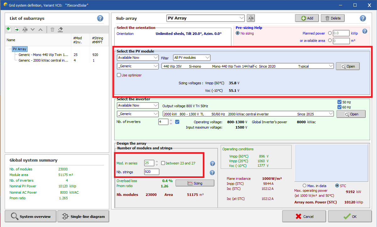
In PVsyst, create a new project and define system parameters that match your PV layout design — particularly:
- Module type
- Number of modules in series
- Number of strings
From the Project window, navigate to Variant → Optional → Near Shadings.
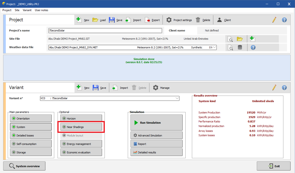
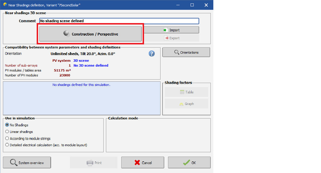
Click Construction / Perspective to open the 3D scene editor.
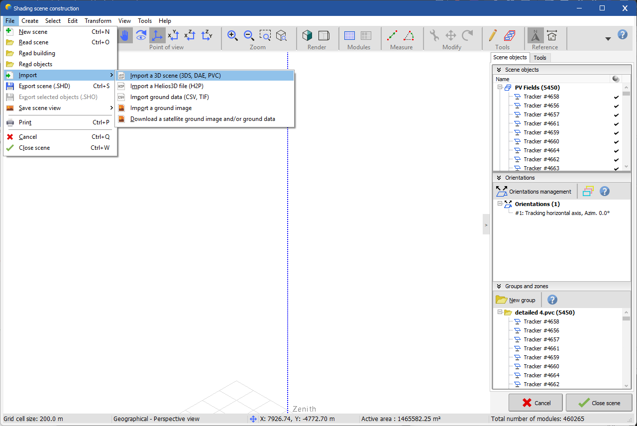
From the top menu, select File → Import → Import a 3D scene, choose your downloaded .pvc file, then select 'OK'.
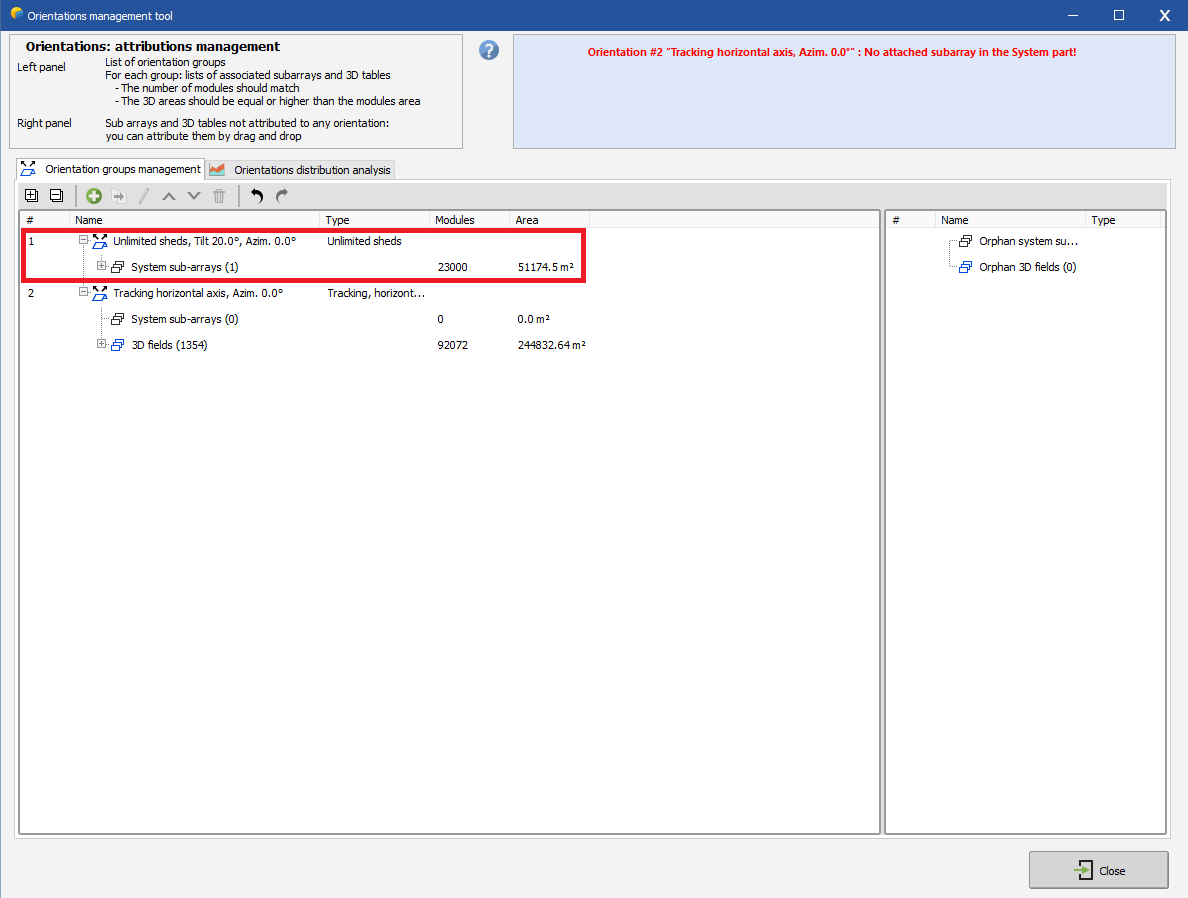
Open Orientations Management from the Tools menu and delete any automatically generated orientation that has (0) 3D fields (i.e. unused orientations).
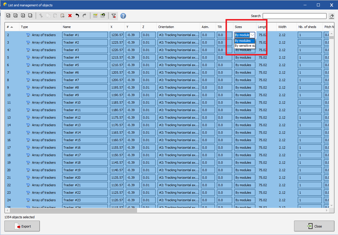
Use the Polygon Select Tool to select all mounting structures in the scene.
Then go to Edit → Modify selected objects (Ctrl + G).
In the edit window, under the Sizes column, select By Modules to apply this setting to all selected structures.
and then close this window.
Double-click any mounting structure (or select one and click Edit Object) to open the 'Detailed Editor'.
In the Tracking Parameters tab, use the Open button to open the orientation settings and enable Backtracking.
![]()
![]()
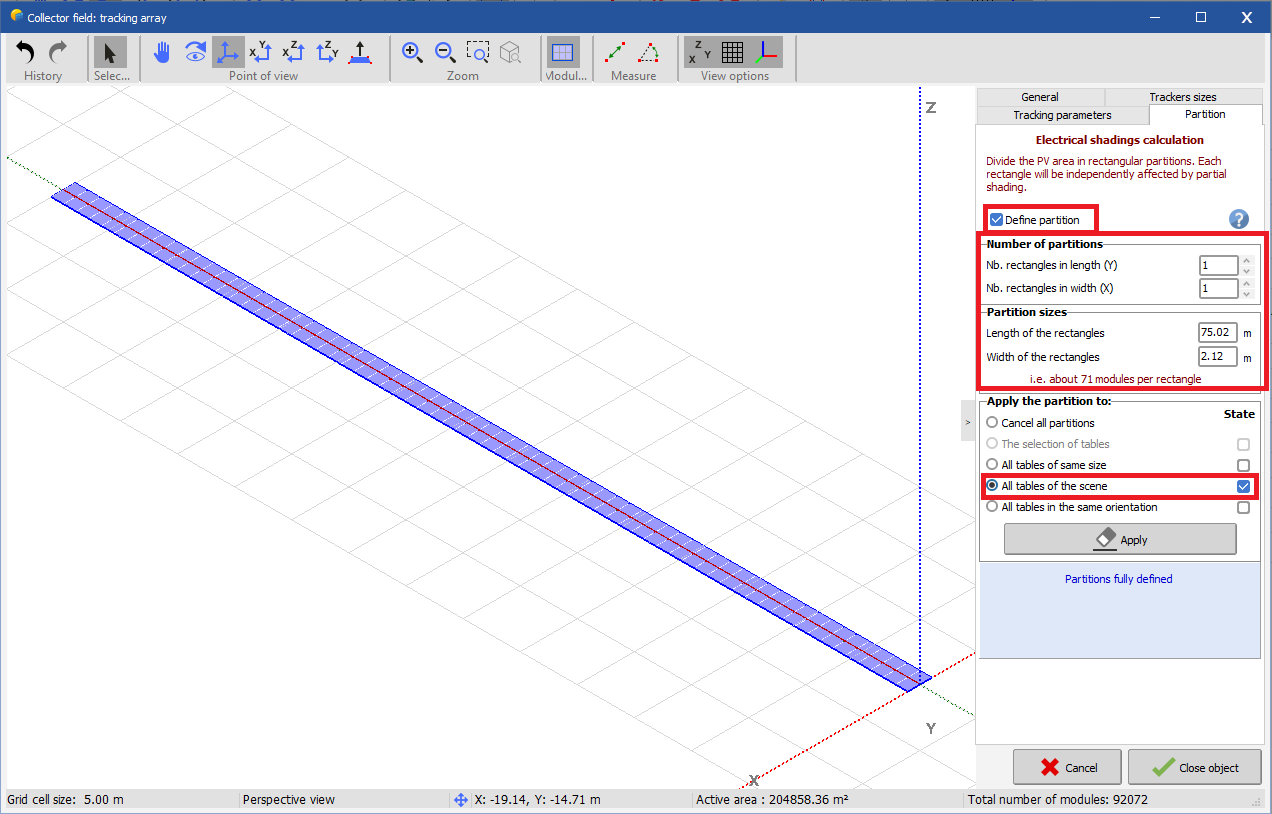
In the Partition tab, define the string partitioning parameters and click Apply to all tables in scene, then close the editing window.
From the top menu, select Tools → Check scene validity and confirm that no errors are reported and close the shading scene window.
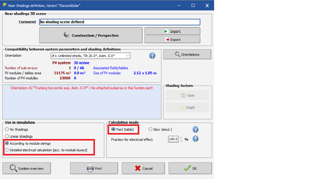
In the Near Shadings definition window, select either According to module strings or Detailed electrical calculation, then click Table to compute the shading factor.
You can download a sample PV Collada export.
⚠️ Sample documents provided here do not represent an actual project site and the information contained in this report should not be relied upon.