Setting up a DXF for AutoPV
In order for a DXF file to upload successfully to AutoPV, the file must have certain features and follow certain naming rules. Follow the steps described on this page to ensure the DXF will be readable by AutoPV.
Note: this guide is written for AutoCAD LT 2025
General
- Components should be defined as AutoCAD blocks.
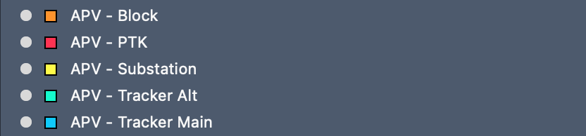
- AutoPV layer names start with
APV, for exampleAPV - Tracker Main.
Required AutoCAD Blocks
- MVS block that has PCU, PTS or PTK in the block name
- Tracker Main
- Substation
Defining attributes
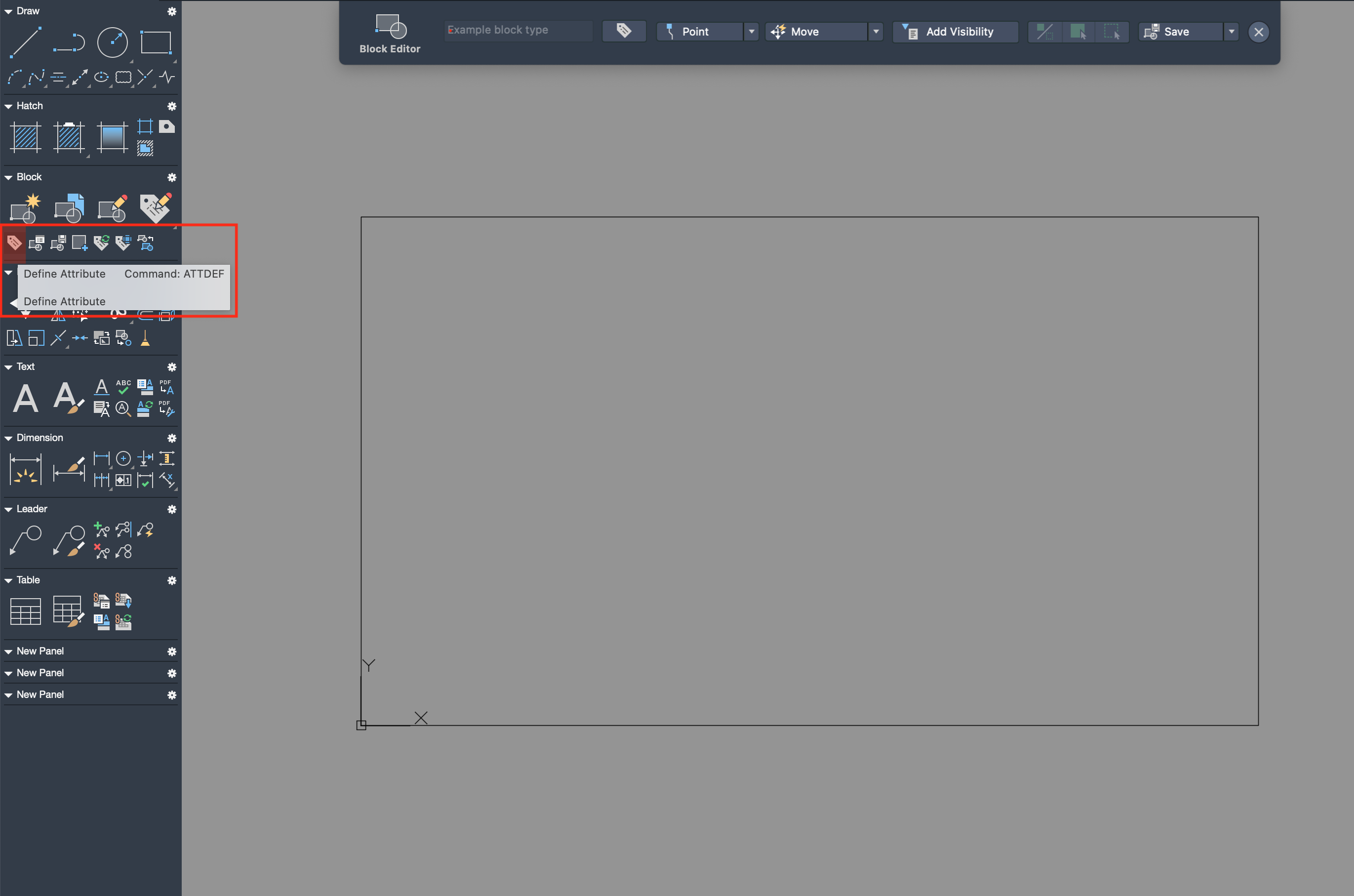
Certain components need specific attributes to be defined. Steps for defining attributes for existing AutoCAD blocks:
- In the Block Editor, select Define Attribute.
-
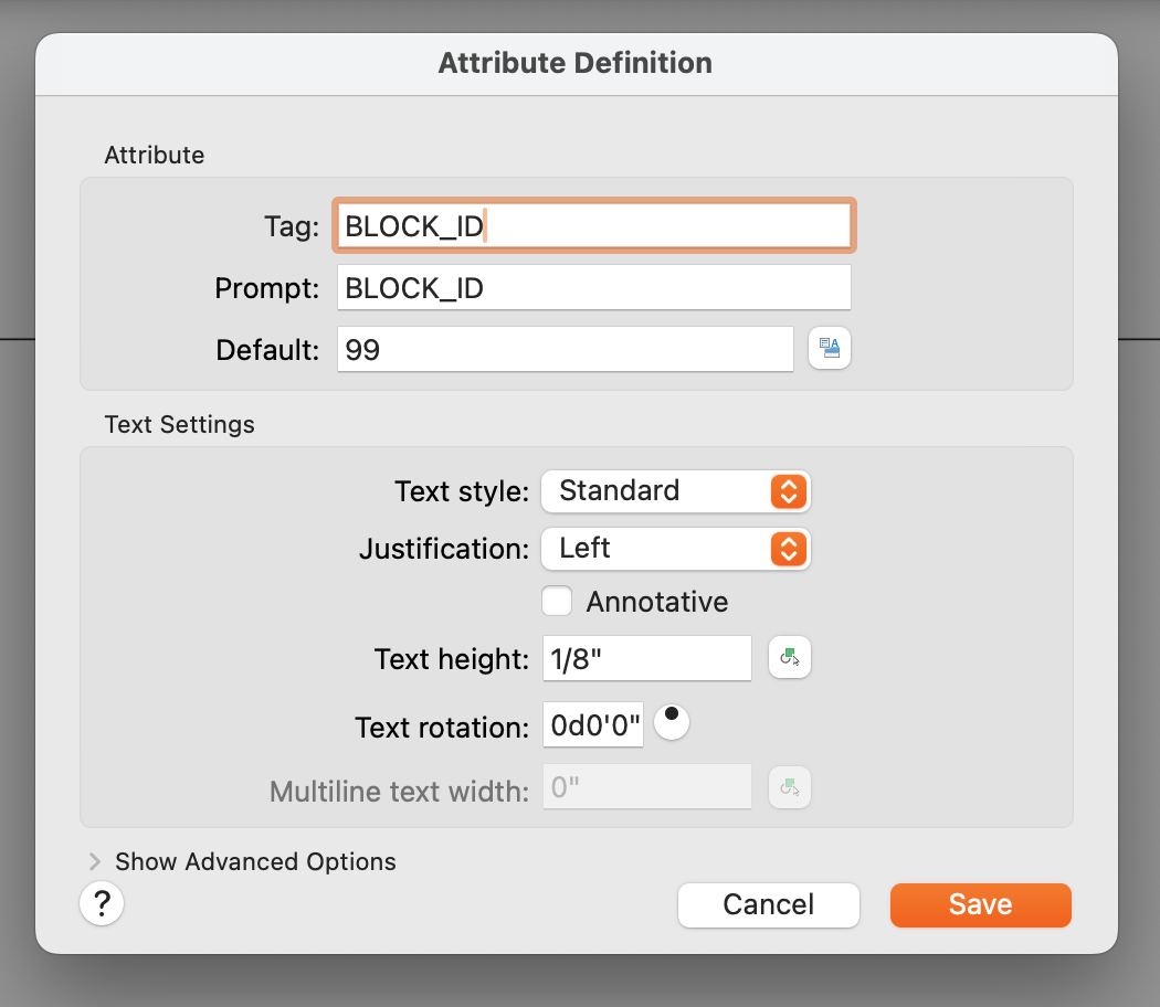
Fill in Tag and Prompt with the attribute name.
-
Set a default value like 99, which will clearly identify which objects have not yet been assigned values.
-
Place the attribute at the bottom left of the block (or above/below previous attributes).
-
Save the changes to the block and exit the Block Editor.
-
Enter command
BATTMAN(Block Attribute Manager) -
Select the correct block from the dropdown menu, and click
Synchronize Blocks.
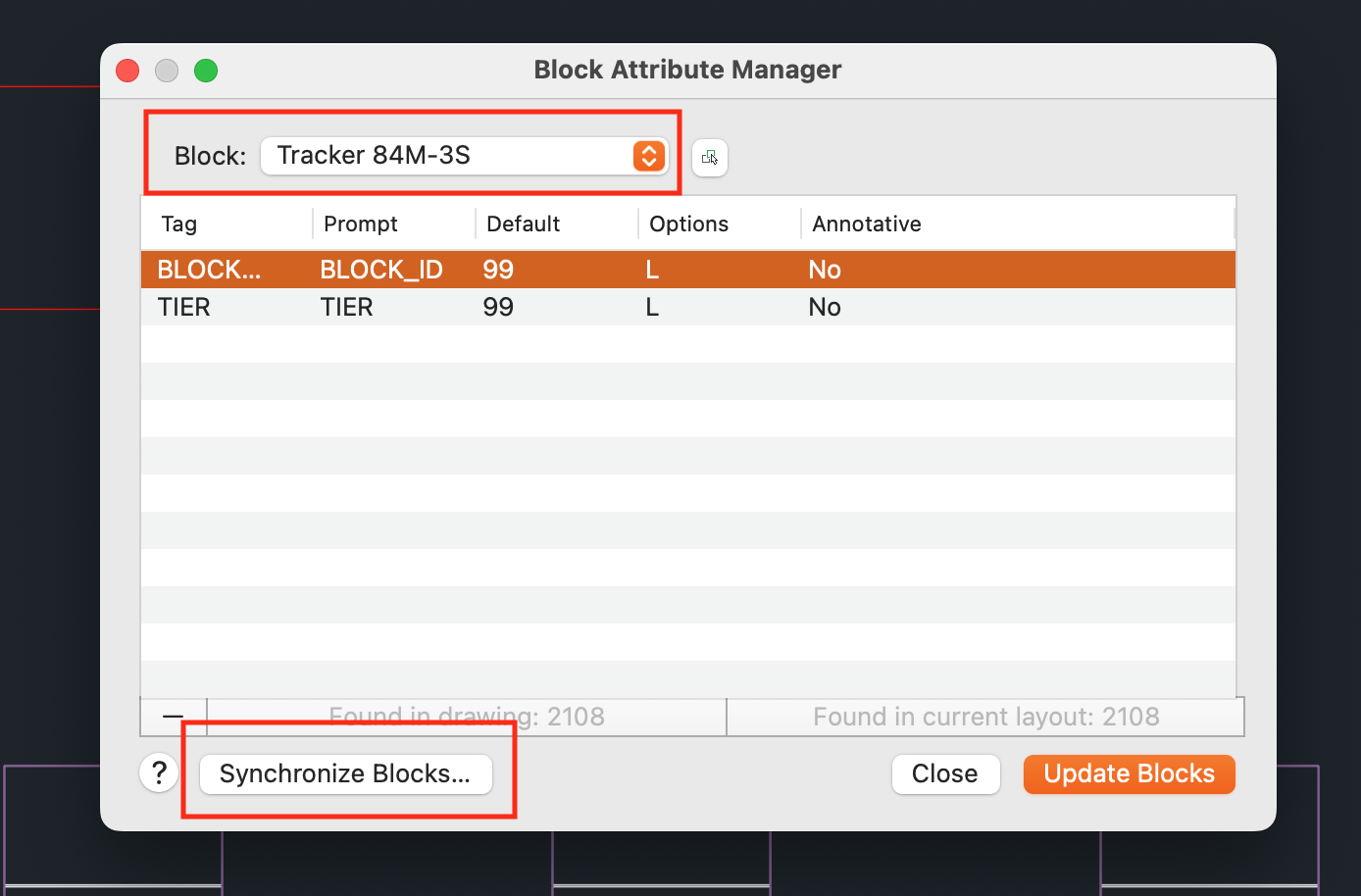
- Update the blocks and close the Block Attribute Manager. All instances of the block should then have the added attributes.
Trackers
- Types of trackers:
- AutoPV currently supports one type of tracker:
Tracker Main. - The main tracker should be on the
APV - Tracker Mainlayer.
- AutoPV currently supports one type of tracker:
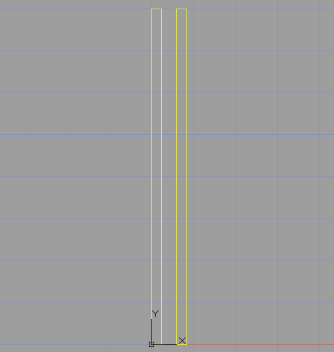
- In the case of dual-row trackers, both tables should be defined in the same AutoCAD block.
-
Required tracker attributes:
TIER(see Defining attributes)- Tracker attributes should be on tracker layer
APV - Tracker Main. - Edit the block in-place and add the tracker attributes.
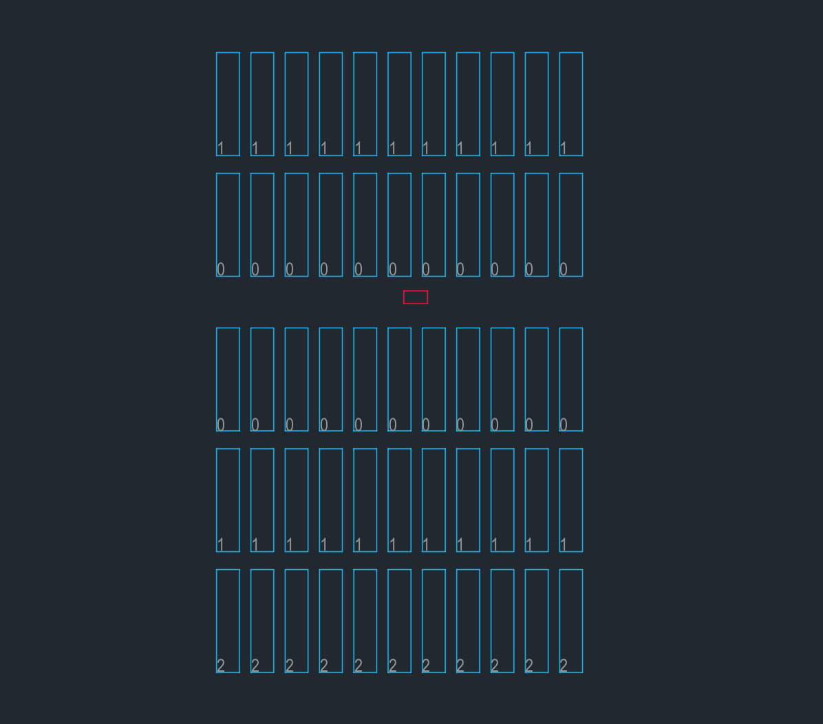
- Tiers are named with a number. Tiers are numbered from 0, starting at the main corridor and moving outward. So in a block with 2 tiers in the North section and 3 tiers in the South section the tiers would be named
1,0,(main corridor),0,1,2when moving from top to bottom.
Trackers with TIERattributes based on position - Tracker attributes should be on tracker layer
-
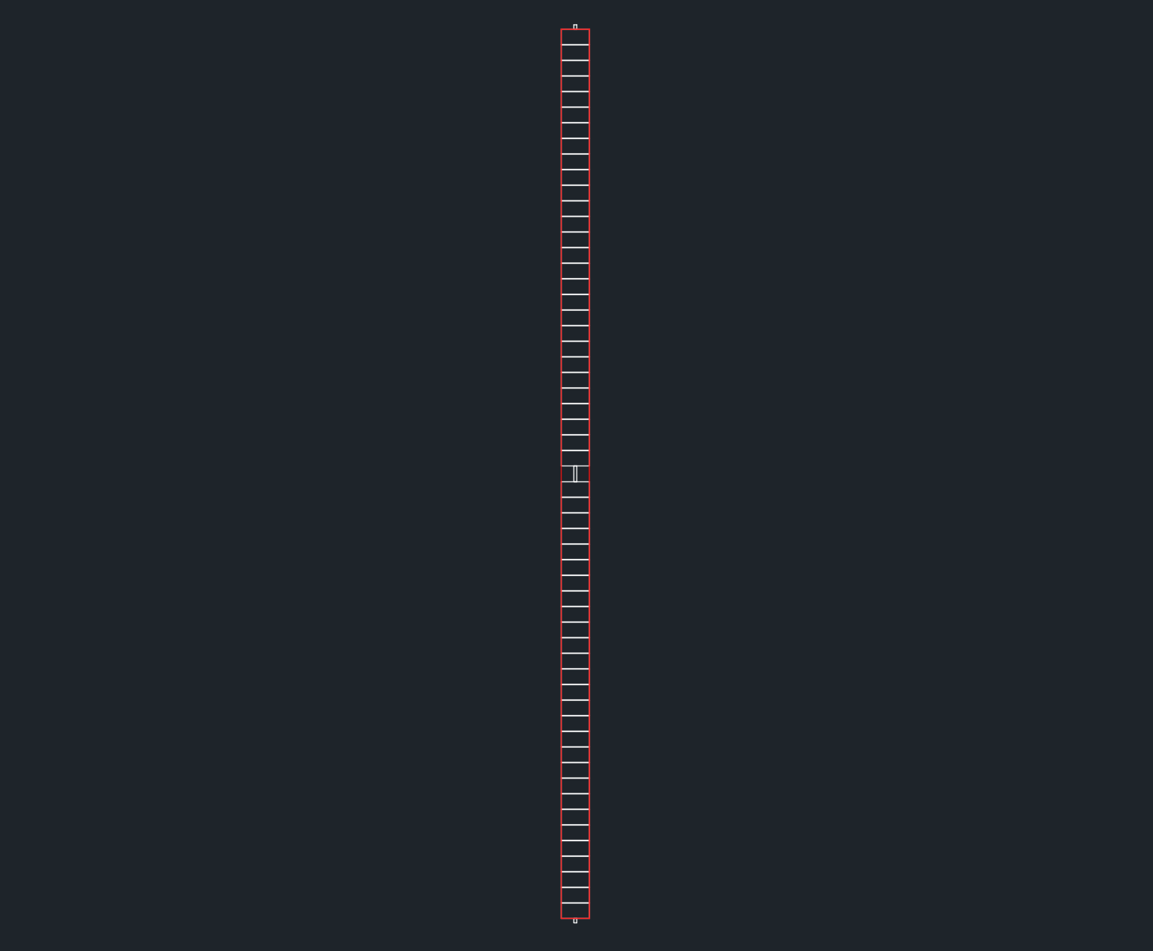
Trackers must have a table borders (AutoCAD polyline - a rectangular polyline is recommended), which follows the edges of the modules and includes all strings. In the case of dual-row trackers each table must have an individual table border. The table borders should be on the appropriate tracker layer (
APV - Tracker Main) .
Medium voltage stations (PCU or PTS)
-
Add a layer called
APV - PCU/PTS(select either PCU or PTS as applicable). -
Ensure the PCU/PTS block is on the
APV - PCU/PTSlayer (i.e. placed on the layer from inside the block editor) and that all instances of the block are on the layer as well. -
There are a number of attributes required to be defined on the PCU/PTS block (see Defining attributes). See a list here, and explanations of the attributes and their possible values further down, at Configuration settings - PCU/PTS attributes. Place the attributes on layer
APV - PCU/PTS.BLOCK_IDCORRIDORMIN_BOXES
Configuration settings - PCU/PTS attributes
⚙️ BLOCK_ID
The number of the PV block (starting from block 1)
Example: 5
⚙️ CORRIDOR
The corridor number. Assign numbers to the main corridors in the site, starting from 1.
Example: 3
⚙️ MIN_BOXES
The target number of inverters or combiner boxes for the block.
Example: 19
The Substation
The substation (both the AutoCAD block definition as well as the block instance) should be on a layer called APV - Substation.
Example
Here is an example of a DXF set up for AutoPV: dxf_example.dxf
This DXF file has extra layers and items that AutoPV will not consume. Only layers and blocks mentioned in this guide will be used by AutoPV.
Tips and Common Issues
Check your spelling. Make sure all required layer names and attributes are named exactly according to the instructions.
Do not rotate or reflect AutoCAD blocks. Before creating an AutoCAD block, ensure that all components are correctly oriented.