Configuring PV Grouping Settings
This guide describes the parameters available to configure the PV grouping algorithm when uploading a DXF:
JB Qty
Junction box refers to string inverters in string inverter and string inverter + architectures. It refers to DC combiner boxes in the central inverter architecture.
The number of junction boxes is limited by the number of inputs available on the PCU (for central inverter architecture) or PTS (for string inverter or string inverter + architecture).
Min Inputs
This parameter is used to prevent low DC/AC ratios on any string inverter in the plant in string inverter and string inverter + architectures.
In central inverter architectures it is used to control the number of DC combiner boxes - a lower value means that more DC combiner boxes can be used for the same quantity of PV strings. For example, in a block with 200 strings, a MIN_INPUT value of 10 would mean the block can have up to 20 DC combiner boxes, and a MIN_INPUT of 8 would mean the block can have up to 25 DC combiner boxes.
Max Inputs
Note that all junction boxes have an inherent maximum input limit, which is specified by the OEM in the datasheet. The value given for the max inputs parameter should not exceed this limit.
This parameter is used to allow some spare inputs on each junction box. For example, for a string inverter with an inherent input limit of 32, a MAX_INPUTS value of 30 would allow for 2 spare inputs on each string inverter.
Max Input Difference
This is used to ensure electrically balanced PV groups. In string inverter and string inverter + architectures it ensures that all string inverters have an equal DC/AC ratio. In the central inverter architecture it reduces the number of different types of DC combiner boxes required in a block.
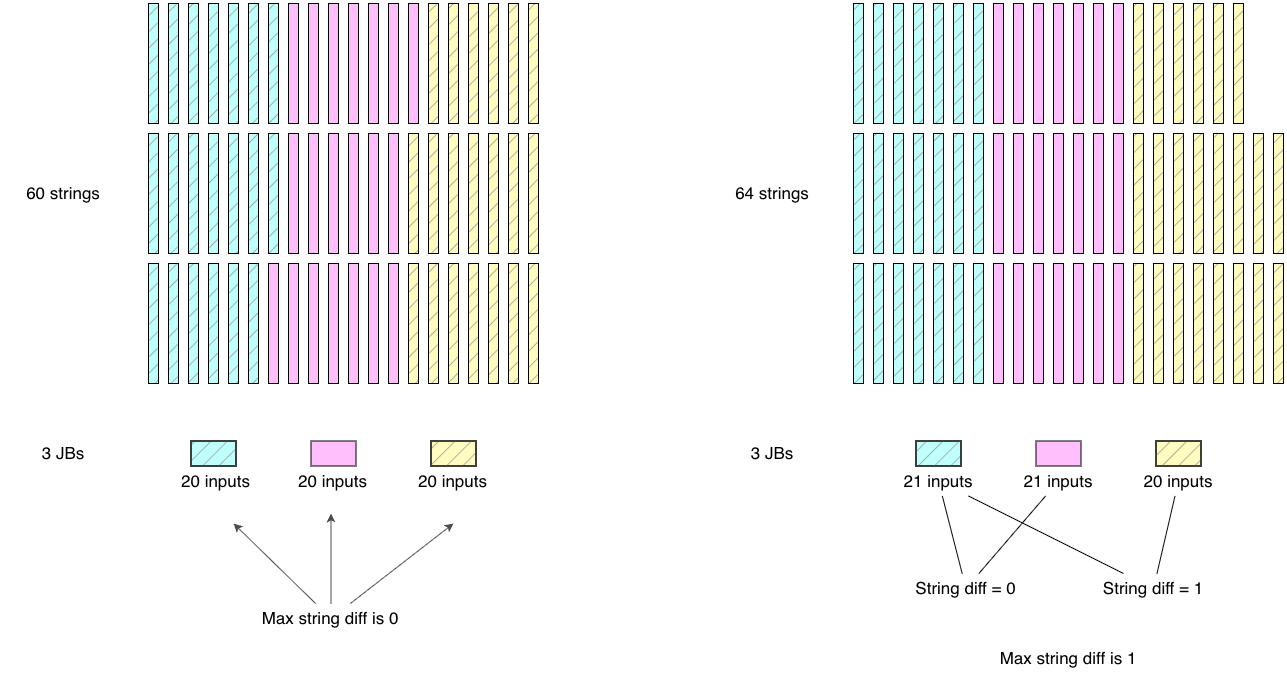
AutoPV provides additional optimizations such as Minimise Crossings that can lead to differences larger than 1 string. The Max Input Difference parameter can therefore be used to prevent large differences between any two junction boxes within a PV block.
Example of PV Grouping With Min Inputs, Max Inputs, and Max Input Difference Constraints:
We set MIN_INPUTS = 20, MAX_INPUTS = 30, and MAX_INPUT_DIFFERENCE = 4. This means that for a given quantity of PV strings and junction boxes in a block, AutoPV will find a value between 20 and 30 where no junction boxes (or PV groups) will have a difference greater than 4 strings.
Block with 400 strings and 20 JBs:
- All JBs should have exactly 20 strings.
- It may not always be possible to have exactly 20 strings in each JB in PV blocks with complex geometry.
- If any JB needs more than 20 strings due to the PV block geometry, then at least 1 JB would need to have less than 20 strings, and since MIN_INPUTS = 20, there is no solution.
Block with 600 strings and 20 JBs:
- If any JB needs more than 30 strings due to the PV block geometry, then at least 1 JB would need to have less than 30 strings. Conversely, if any JB needs to have less than 30 strings, then at least 1 JB would need more than 30 strings. Since MAX_INPUTS = 30, there would be no solution.
Block with 520 strings and 20 JBs:
- 520 / 20 = 26. If any JB needs more than 26 strings, then at least one JB would need to have less than 26 strings. Since MIN_INPUTS = 20 and MAX_INPUTS = 30, AutoPV can therefore find a value between 20 and 30 for each junction box (or PV group) such that the difference between any two JBs (MAX_INPUT_DIFFERENCE) is no greater than 4 strings.
Minimise Crossings
AutoPV provides an optimization parameter to control the amount of cables crossing minor corridors. This is also an optimization between electrically balanced groups and ease of construction.
- Minimise crossings - ☑︎ checked : This reduces the number of cables crossing the corridors which favours easier construction but less electrically balanced PV groups.
- Minimise crossings - ☐ unchecked: This removes the consideration of cables crossing the corridors and provides the most electrically balanced groups regardless of construction complexity. Based on the block shape and complexity, this option may not always produce a solution.
Summary
Given the complexity of PV sites and the resulting PV array layouts that are developed, being able to obtain the most electrically balanced plant while maintaining ease of construction can be near to impossible to achieve using traditional methods.
AutoPV therefore provides an analytical solution to this problem that results in the most optimized solution for any given PV Array which would not be humanly achievable using traditional methods. And it does this in seconds.
Tips and Troubleshooting
If the 'min inputs' and 'max inputs' are set to the same value (e.g. MIN_INPUTS = MAX_INPUTS = 22), the algorithm will try to ensure that all inverters have exactly that number of strings (22) connected. However, this may not be possible for the given layout based on its geometry. Try disabling the 'minor crossings' option as a first step. If that doesn't work then try reducing the min inputs so that there's some difference between the min and max inputs.