Configuring a DXF from an Empty Drawing
AutoPV can easily import PV layout designs from DXF files. This guide describes how to configure a PV layout design starting with an empty georeferenced DXF file.
It is recommended to use AutoCAD to configure PV layout designs as it is generally the easiest for beginners. However, other CAD tools as well as some GIS tools can also be used.
ℹ️ This guide is based on utilizing AutoCAD LT running on Windows. Other versions of AutoCAD running on different platforms can also be used although their functions may be different.
Pre-requisites
- Georeferenced DXF file (see Creating a Georeferenced CAD File)
- An understanding of basic CAD operations (see Basic CAD Operations for Configuring DXF PV Layout Designs)
Minimum Requirements
AutoPV only requires the following 3 design features to be configured in the DXF:
- PV Tracker
- MVS (PTS or PCU)
- Substation
PV Tracker
Requirements
- Object type: Polyline as a block reference
- Layer name:
APV - Tracker Main - Attributes:
TIER,BLOCK_ID
Creating a PV Tracker
To create a PV Tracker, start by drawing a closed polyline or use the rectangle tool to draw a rectangular shape that represents the PV Tracker. The width of the tracker should be equal to the length of the PV module selected and the length of the tracker should equal the resulting length when considering the no. of modules in series, no. of strings mounted on the tracker, module gap and motor gap.
E.g. given the following:
- PV module dimensions: 2.103 (l) x 1.102 (w) m
- No. of modules in series: 30
- No. of PV strings: 3
- Module gap: 0.02 m
- Motor gap: 0.5 m
The tracker length can be obtained from AutoPV by creating a new tracker using the tracker configurator tool with the above parameters or by using the following formulae:
-
Total no. of modules = No. of modules in series x No. of PV strings
-
Tracker length = Total no. of modules x PV module width + (Total no. of modules - 2) x Module gap + motor gap
For the above example:
-
Total no. of modules = 30 x 3 = 90
-
Tracker length = 90 x 1.102 + (90 - 2) x 0.02 + 0.5 = 101.44 m
Next, place the drawn polyline on the APV - Tracker Main layer by selecting the polyline and choosing the layer from the dropdown list:
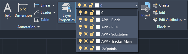
(see Basic CAD Operations for Configuring DXF PV Layout Designs for creating layers)
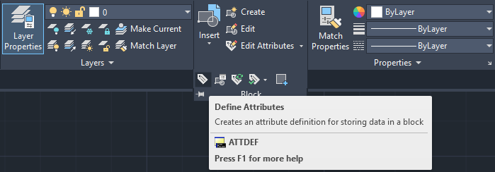
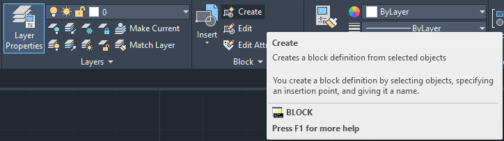
Add the necessary attributes by clicking the Define Attributes button in the Block group of the home tab or by typing the command ATT followed by the Enter key.
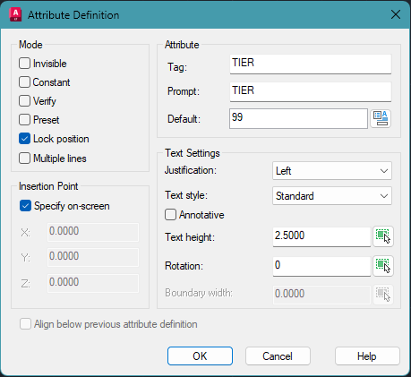
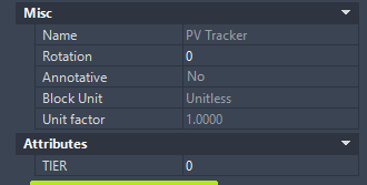
Create an attribute for TIER. Insert the parameter name in the Tag and Prompt field and specify any default value in the Default field. Click OK on the prompt and place the attribute label anywhere near to the polyline. Near the bottom left corner is usually a good location.
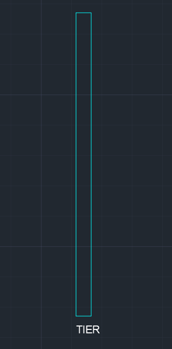
TIER AttributeSimilarly, create an attribute for BLOCK_ID by repeating the above steps.
Finally, create a block reference for the PV Tracker by selecting the polyline, TIER and BLOCK_ID attributes then click the Create button in the Block group of the home tab or by typing the command block followed by the Enter key. The block creation window will be displayed.
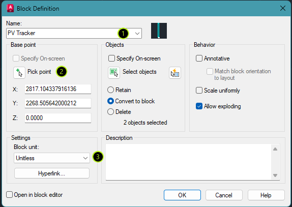
Specify any name in the Name field then click Pick point to define the origin point of the block reference. Click on the bottom left corner point of the polyline when prompted. Ensure that object snapping is turned on to precisely select the corner point.
Set the units to unitless then click OK.
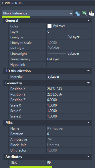
Selecting the object and viewing its properties should now display the object as a Block Reference with the TIER and BLOCK_ID attributes in the Attributes section.
Lastly, select the object (block reference) and place it on the APV - Tracker Main layer.
This tracker can now be used for generating PV layouts by using the copy/paste tool or the array tool to quickly fill sites.
⚠️ If the array tool is used, selecting a tracker will select the entire array of trackers and the properties window will show the object type as an array. To remove this grouping, select the array then type explode to use the explode command. Individual trackers should be selectable again and their object type should be displayed as a block reference in the properties window.
ℹ️ For dual-row trackers, start by drawing 2 polylines that represent the 2 PV tables spaced apart by pitch. Then follow the same steps above. Both polylines should be contained in a single block reference. Also note the difference in tracker length. The total no. of modules should be divided by 2 before calculating the tracker length to obtain the correct length.
Assigning attribute values to PV Trackers
After a PV layout has been designed from the newly created tracker, the final step is to assign a value to the TIER and BLOCK_ID attribute for each tracker.
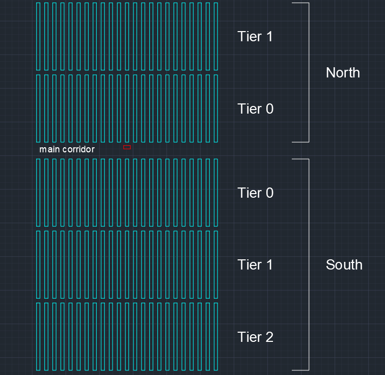
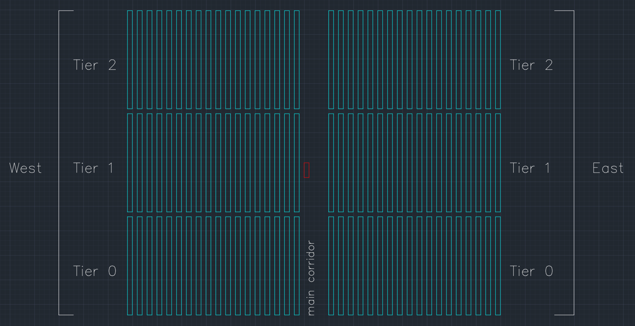
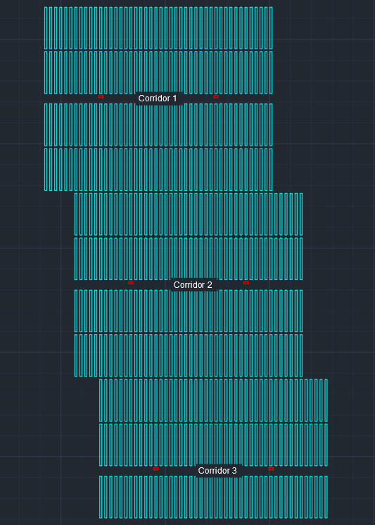
A PV block is defined as a number of trackers connected to a single MVS i.e. a PV block can only have 1 MVS. A PV block is divided into a north and south section, or into a west and east section, by a main corridor. A TIER is defined as a single row of trackers surrounded by main or minor corridors.
For layouts where main corridors run from west to east (i.e. blocks have a north and south section), tier numbers increase in the direction away from the main corridor. The first row of trackers north of the main corridor will therefore be Tier 0, the second row will be Tier 1, the third row will be Tier 2, and so forth. Similarly, the first row of trackers south of the main corridor will be Tier 0, the second row will be Tier 1, the third will be Tier 2, and so forth.
For layouts where main corridors run from north to south (i.e. blocks have a west and east section), tier numbers increase from south to north. The south-most row of trackers in the west section will be Tier 0, the row above it will be Tier 1, and so forth. In the east section the tier numbering will also start at the south-most row of that section, which will be Tier 0.
To assign a value to the TIER and BLOCK_ID attribute, simply select the relevant tracker(s) and insert an integer value (0, 1, 2, etc.) for the TIER and BLOCK_ID attribute in the properties window respectively. Note that the BLOCK_ID needs to have a value of 1 or greater i.e. a BLOCK_ID of 0 is unreadable.
TIER & BLOCK_ID Attribute ValueTrackers are now fully defined and ready to import into AutoPV.
MVS
Requirements
- Object type: Polyline as a block reference
- Layer name:
APV - PCUfor central inverter plants ORAPV - PTSfor string inverter plants - Attributes:
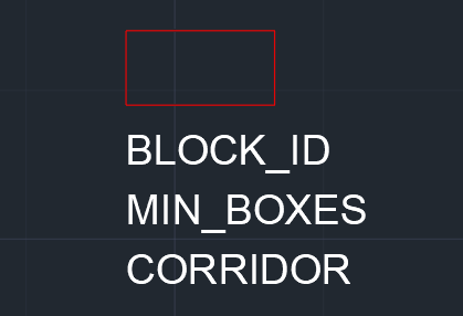
BLOCK_ID,MIN_BOXES,CORRIDOR
Creating an MVS
To create an MVS, start by drawing a closed polyline or use the rectangle tool to draw a rectangular shape that represents the MVS. The width and depth should match the dimensions shown in the datasheet for the selected MVS.
Next, place the drawn polyline on the APV - PCU layer if a central inverter plant is being designed or the APV - PTS layer if a string inverter or string inverter+ plant is being designed. This can be done by selecting the polyline and choosing the layer from the dropdown list.
Add the necessary attributes by clicking the Define Attributes button in the Block group of the home tab or by typing the command ATT followed by the Enter key.
Create attributes for BLOCK_ID, MIN_BOXES and CORRIDOR. Insert the parameter name in the Tag and Prompt field and specify any default value in the Default field. Click OK on the prompt and place the attribute label anywhere near to the polyline. Near the bottom left corner is usually a good location.
Finally, create a block reference for the MVS by selecting the polyline and all attributes then click the Create button in the Block group of the home tab or by typing the command block followed by the Enter key. The block creation window will be displayed.
Specify any name in the Name field then click Pick point to define the origin point of the block reference. Click on the bottom left corner point of the polyline when prompted. Ensure that object snapping is turned on to precisely select the corner point.
Set the units to unitless then click OK.
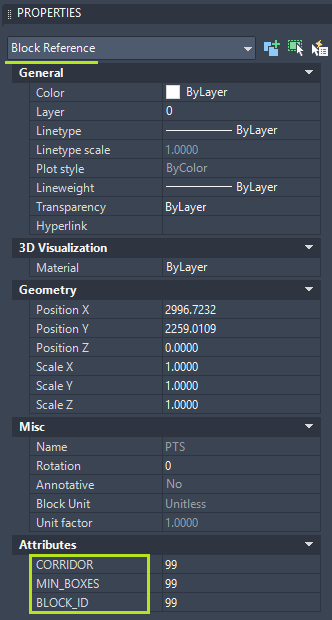
Selecting the object and viewing its properties should now display the object as a Block Reference with the BLOCK_ID, MIN_BOXES and CORRIDOR attributes in the Attributes section.
Lastly, select the object (block reference) and place it on the APV - PCU or APV - PTS layer (whichever is relevant).
This MVS can now be used for generating PV layouts by using the copy/paste tool.
Assigning attribute values to MVS units
After a PV layout has been designed from the newly created MVS, the final step is to assign values to the BLOCK_ID, MIN_BOXES and CORRIDOR attributes.
Simply select the relevant MVS and insert an integer value (1, 2, 3, etc.) for the BLOCK_ID attribute in the properties window. BLOCK_ID refers to the PV block that the MVS belongs to. A PV block is defined as a number of trackers connected to a single MVS i.e. a PV block can only have 1 MVS.
Similarly, insert an integer value (1, 2, 3, etc.) for the MIN_BOXES attribute in the properties window. MIN_BOXES represents the no. of DC-DC combiner boxes connected to the PCU in central inverter plants or the no. of string inverters connected to the MVS for string inverter or string inverter+ plants. Varying values can be used for each MVS but the total should equal the total no. of DC-DC combiner boxes or strings inverters used for the plant.
E.g. if the plant is to be designed with 100 string inverters and 4 PV blocks, then the MIN_BOXES attribute can be set to 25 on each MVS. If different values were to be used for each MVS, then we would need to ensure that the total still equals 100 and the MVS has sufficient inputs to accept the specified qty of MIN_BOXES by referring to the datasheet of the selected MVS.
Lastly, insert an integer value (1, 2, 3, etc.) for the CORRIDOR attribute in the properties window. CORRIDOR refers to the main corridor in which the MVS is located. After the PV layout has been designed, each MVS will be located within a main corridor. These should be numbered starting at the northern-most corridor of the site.
The MVS units are now fully defined and ready to import into AutoPV.
Substation
Requirements
- Object type: Polyline as a block reference
- Layer name:
APV - Substation - Attributes: None
Creating a Substation
To create a Substation, start by drawing a closed polyline or use the rectangle tool to draw a rectangular shape that represents the Substation. A typical size is 100 x 100 m.
Next, place the drawn polyline on the APV - Substation layer by selecting the polyline and choosing the layer from the dropdown list.
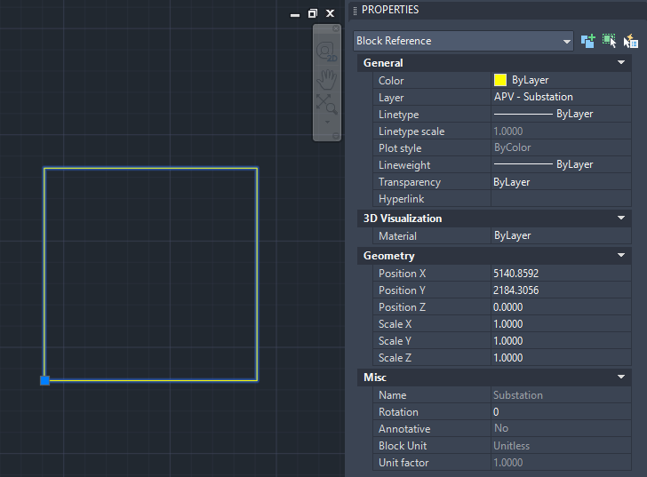
Create a block reference for the Substation by selecting the polyline then clicking the Create button in the Block group of the home tab or by typing the command block followed by the Enter key. The block creation window will be displayed.
Specify any name in the Name field then click Pick point to define the origin point of the block reference. Click on the bottom left corner point of the polyline when prompted. Ensure that object snapping is turned on to precisely select the corner point.
Set the units to unitless then click OK.
Selecting the object and viewing its properties should now display the object as a Block Reference.
Lastly, select the object (block reference) and place it on the APV - Substation layer.
This Substation can now be used in PV layout designs by using the copy/paste or move tool. Ensure that the PV layout design only contains 1 Substation placed at the required location.
The PV layout design is now fully configured and ready to import into AutoPV!
Summary
The general process for configuring design features as block references can be summarised as follows:
Draw a polyline representing the feature -> Assign the polyline to the correct layer -> Define attributes -> Create a block reference -> Assign attribute values
Summary of Minimum Requirements
| Design Feature | Object Type | Layer Name | Attributes | Example Values |
|---|---|---|---|---|
| PV Tracker | Polyline as a block reference | APV - Tracker Main |
TIER, BLOCK_ID |
TIER = 0, BLOCK_ID = 1 |
| MVS | Polyline as a block reference | APV - PCU OR APV - PTS |
BLOCK_ID, MIN_BOXES, CORRIDOR |
BLOCK_ID = 1, MIN_BOXES = 24, CORRIDOR = 2 |
| Substation | Polyline as a block reference | APV - Substation |
--- | --- |
Example DXF
The following example DXF is fully configured and can be used as a guide:
Tips and Common Issues
Check your spelling. Ensure all required layer names and attributes are named exactly as per this guide including spaces and uppercase or lowercase letters.
Ensure that block references have an x, y and z scale of 1. Using negative scales or values other than 1 may result in shifted or distorted layouts.
For N-S layouts, ensure that tier numbers are numbered sequentially starting at 0 without any skipped numbers e.g. 0, 1, 2, 3 instead of 1, 2, 4, 5.
It is recommended to set the drawing's units to unitless and ensure that all block references created are also set to unitless. This prevents blocks from scaling when inserting /pasting them into the drawing. In AutoCAD, this setting can be found by clicking the 'A' symbol in the top left -> drawing utilities -> units.
Do not rotate or reflect block references. Before creating a block reference, ensure that all drawn geometry (e.g. polylines) are correctly orientated. Rotation values should be 0 when viewed in the properties window. The MVS may howewer be rotated by 90° if required.