Basic CAD Operations for Configuring DXF PV Layout Designs
This guide covers basic CAD operations needed to configure a DXF PV Layout design for importing into AutoPV.
ℹ️ This guide is based on utilizing AutoCAD LT running on Windows. Other versions of AutoCAD running on different platforms can also be used although their functions may be different.
Drawing Basic Shapes
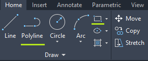
AutoCAD has many different drawing tools, however the only drawing tool required for configuring PV layout designs for AutoPV is the polyline tool. This can be found on the Home tab in the Draw group or by typing polyline and pressing Enter.
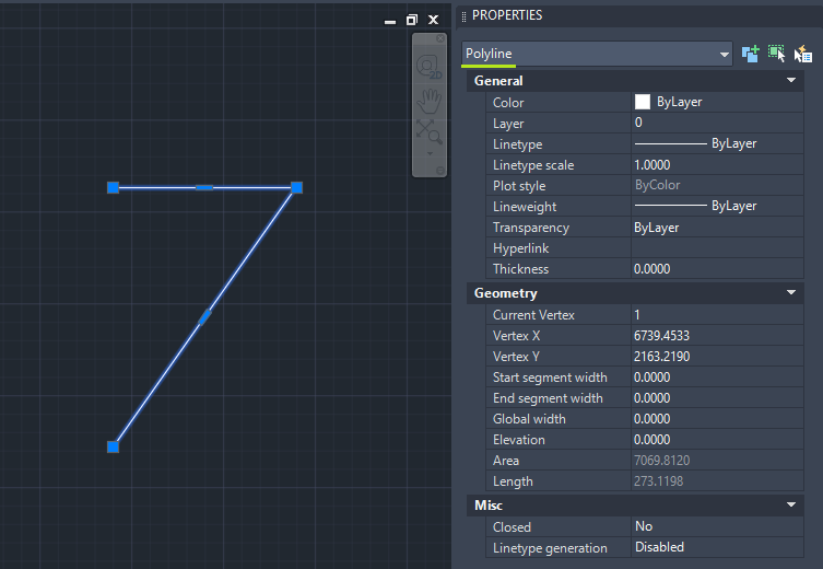
All drawn shapes should be closed polylines which means that the last point clicked should co-incide with the first point clicked. Using tools such as the rectangle tool will automatically result in a closed polyline.
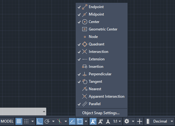
To ensure that the mouse snaps to an exact point on drawn geometry, AutoCAD's object snapping feature can be toggled on / off by pressing the F3 key on the keyboard or by clicking the object snap icon in the lower right.
Objects can be selected by clicking on them or clicking anywhere within the model space followed by moving the mouse to initiate the polygon select tool. Deselecting objects and exiting commands can be done by pressing the escape key on the keyboard. Commands can be repeated by pressing the spacebar key.
The Copy tool is useful for copying individual objects and placing them precisely. Simply select an object, click the Copy button and follow the onscreen prompts.
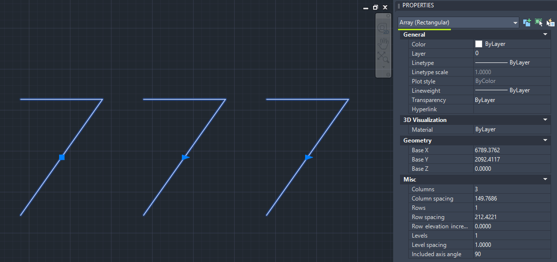
The Array tool can be used for duplicating multiple objects with fixed spacing and is useful for very quickly filling a site with PV Trackers. Select an object, click the Array button, then specify the array settings. For designing PV plants, typical settings would be to set the row count to 1, the column count to the number of PV Trackers and the Between input to the pitch value.
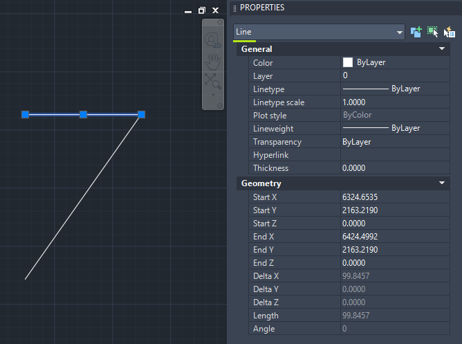
⚠️Avoid using the line tool as this creates individual lines even if closed shapes are drawn.
ℹ️AutoCAD's Ortho mode can be toggled on / off by pressing F8 which constrains all commands such as drawing and moving objects in a straight x or y direction.
Viewing Properties
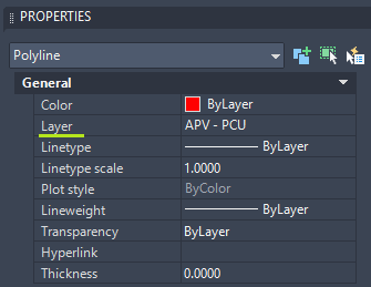
All drawn geometry in AutoCAD have a specific object type. To view the object type of drawn geometry, open the properties window by clicking the Properties button in the View tab then select the object.
When geometry is modified using other tools, the object type may change. For example using the array tool on a polyline creates an array of polylines. Selecting any polyline within the array selects the entire array and the object type is shown as array.
To remove the array grouping, the explode command can be used by selecting the array then typing explode followed by pressing the Enter key. Individual polylines will be selectable again and their object type will be shown as polyline.
Key Concepts for Configuring PV Layout Designs
There are 3 key concepts used for configuring PV layout designs for AutoPV:
- Layers
- Block References
- Attributes
Layers
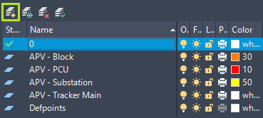
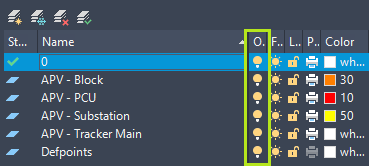
Any drawn geometry or objects can be placed on a layer. The default layer is named 0. Any drawn geometry or inserted objects will be placed on the currently selected layer shown in the dropdown list.
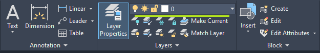
Create a new layer by opening the Layer Properties Manager window, then click the New Layer button.
An object's layer can be changed by selecting the object then choosing the layer from the dropdown list.
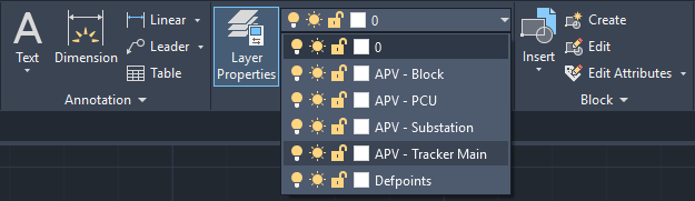
Viewing which layer a particular object is currently on can be done by selecting the object and viewing the dropdown selector or the Layer property in the properties window.
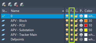
💡Tip: The lightbulb button in the Layer Properties Manager window can be used to turn a layer on / off. This can be used to confirm whether drawn geometry is on the correct layer.
Block Reference
Any drawn geometry or objects can be placed in a container called a block reference (typically referred to as an AutoCAD block).
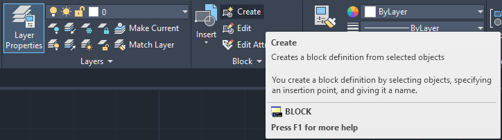
Create a block reference by selecting the relevant drawn geometry then click the Create button in the Block group of the home tab or by typing the command block followed by the Enter key. The block creation window will be displayed.
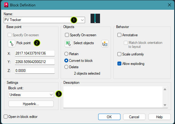
Specify a name for the block reference in the Name field then click Pick point to define the origin point of the block reference. Select an origin point when prompted. The bottom left corner point of drawn geometry is usually the preferred origin point. Ensure that object snapping is turned on to precisely select a point on drawn geometry.
Set the units to unitless then click OK.
Once the block reference has been created, select it and place it on the same layer as the drawn geometry by selecting the relevant layer from the dropdown list.
⚠️Note that the block reference (container) itself can be placed on a different layer to the drawn geometry contained within the block. The block reference will default to the currently selected layer when created, which is usually layer 0. Ensure that all drawn geometry as well as their corresponding block reference (container) are on the same layer by firstly placing all drawn geometry on their relevant layers before creating the block.
ℹ️The layer of the drawn geometry contained within the block reference can be changed by editing the block reference. A block reference can be edited by selecting the block reference, right-clicking to open the context menu then choosing the Edit Block In-place command. This will make the drawn geometry within the block reference selectable. Select the geometry and change the layer by selecting the relevant layer from the layer dropdown list. Click the Save Changes button in the top right section of the Home tab.
💡Tip: the Freeze button in the Layer Properties window can be used to turn block references on / off. This can be used to confirm whether block references are on the correct layer.
Attributes
Attributes are parameters that can be assigned to block references. Multiple attributes can be applied to the same block reference to indicate different parameters.
Attributes can be added before or after block creation. To add an attribute before block creation:
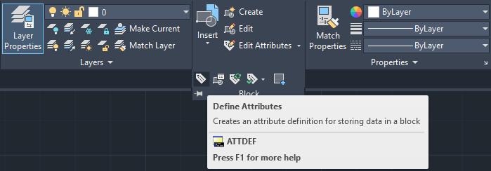
- Click the
Define Attributesbutton in theBlockgroup of the home tab or type the commandATTfollowed by theEnterkey.
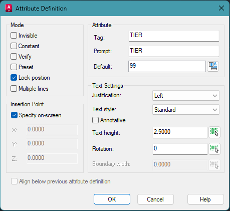
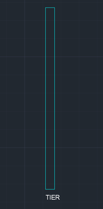
- Insert the parameter name in the
TagandPromptfield and specify any default value in theDefaultfield. ClickOKon the prompt and place the attribute label anywhere near to the drawn geometry. Near the bottom left corner is usually a good location.
To add attributes after block creation:
- Select the block reference, right-click to open the context menu then select the
Edit Block In-Placecommand. ClickOKon the reference edit window that opens. - Click the
Define Attributesbutton in theBlockgroup of the home tab or type the commandATTfollowed by theEnterkey. - Insert the parameter name in the
TagandPromptfield and specify any default value in theDefaultfield then clickOK. - Click the
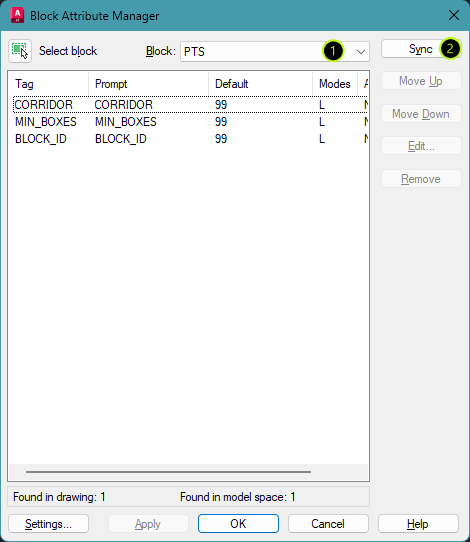
Save Changesbutton in the top right section of theHometab. - Type the command
BATTMANto open the block attribute manager. Select the relevant block from theBlockdropdown list then click theSyncbutton to update the block with the newly created attributes. ClickOKto close the window. The attribute should now be visible within the block.
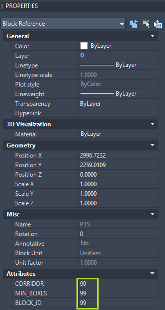
To assign a value to an attribute, select the block reference(s) and insert or change the value in the relevant attribute field in the Properties window.
💡Tip: Attributes can be placed on any layer however it may be beneficial to place them on a single layer typically called attributes or similar.